CONTENT
- Introduction
- General Definition
- Principle Of Operation And Design Considerations
- Beam Shaping: Single-Mode Versus Multi-Mode
- High Homogeneity Series (RH/HH/XH)
- Application Example - Optical Setup With MM Fiber
- Installing / Sensitivity for Mechanical Tolerances
- FAQs
- Instruction For Using VirtualLab BlackBox Models
- Diffuser Standard Products
- Download PDF

INTRODUCTION

An optical Diffuser/Homogenizer (DF/HM) transforms a single or multi-mode input beam into a well-defined output beam, characterized with a desired shape, and homogenized flat-top intensity (or other intensity profile, see below).
Holo/Or’s optical diffuser, either diffractive or broadband, is mainly used for high power laser applications, when uniform exposure is needed, with accurately defined sharp shaped edges, while enabling high efficiency.
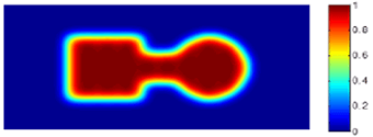
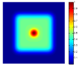
The most common diffuser shapes are: round, square, rectangular, elliptical and hexagonal, however, almost any shape of image can be designed. It is also possible, to tailor the intensity distribution of the image, so that different areas receive more/less energy, as in the picture at the right.
Click here and contact us for more information.
Typical features and applications
features
- Works with single or multi-mode input beams
- Glass or plastic materials
- NO centration requirement
- Any output shape or symmetry
- Uniform/Tailored intensity profile
- Small transfer region
- Exact diffusion angles
- Single element / surface
Applications
- Beam homogenizing/shaping
- Laser material processing: perforation, ablation, derailing, marking, scribing and welding
- Medical/aesthetic laser treatment
- Beam shaping for Excimer lasers
- Hot spot reducer
Specifications
| Materials: | Fused Silica, Sapphire, ZnSe, Polymer on Glass, Plastics |
| Wavelength range: | 193[nm] to 10.6[um] |
| DOE design: | Binary (2-level) and up to 16-levels |
| Diffraction efficiency: | 75% – 98% |
| Element size: | 2[mm] to 100[mm] |
| Coating (optional): | AR/AR Coating |
| Custom Design: | Tailored shape and intensity distribution |
| Pattern angles @532[nm]: | Few mRad to ~41deg |
General definition
A diffractive diffuser (HM) splits incident beam in semi random directions in order to achieve a desired shape of intensity profile in the far field or focal plane.
This method enables to design an element that will produce any arbitrary shape, intensity profile with precise angle and size of the output.
The diffuser performance strongly depends on the incident beam parameters. In general, one can distinguish between two qualities:
- Highly coherent beam (and quasi-single mode) with M2 <~5
- Multi-Mode laser beams (with M2 > 5)
Best results in terms of intensity profile, uniformity, efficiency and transfer region for single-mode lasers can be achieved by using Top Hat (TH) designs.
When the incident beam is more complex to define – by having an arbitrary intensity distribution and not a near-to-perfect Gaussian (higher M2) one, diffractive optical diffusers become the preferred solution.
Examples of custom shapes
In addition to basic shapes as square, rectangular, round, elliptical, and line we can design any arbitrary shape. Below we show a few examples as illustration:

Principle of operation and design considerations
1. Minimum required parameters needed to chose/design a diffuser:
- Wavelength
- Output shape and intensity profile (Flat-top or customized)
- Divergence angle (of output shape) or image size and EFL
- Beam quality (M2)
2. Common diffuser/homogenizer elements are manufactured on a DOE window. Since the diffuser defines a certain diffusion angle, the customer is able to control the image size on the image plane by choosing a focusing lens with a correct EFL. Typical setup includes: a laser, a Homogenizer/Diffuser DOE and a focusing lens as presented below:

3. The optical parameters of the diffuser can be easily calculated from geometric point of view:
 See also our interactive optical calculator for Diffuser/Homogenizer.
4. Holo/Or has the capability to design an integrated solution by combining a DOE window and a specific focusing lens into one single hybrid element. Here, the diffractive pattern will be etched on the Plano side of the focusing lens (plano-convex lens). The advantages of this solution include less optical surfaces, compact dimension and low weight.
5. The minimum diffusion angle is equivalent to approximately 5-10 times the diffraction-limit. In addition, a larger angle ratio (to a certain level) will increase the performance quality. The formula for the diffraction-limited spot diameter at 1/e2 (D.L.spotsize) follows:

L = Working distance
λ = Wavelength
D = Input beam size on focusing element
M2= Beam quality value of input laser beam
6. The edges of the diffused beam are generally steep and well defined. The ratio between input divergence angle to the HM’s diffusion angle, determines the ratio of the transition region to the well-homogenized region of the output beam.
7. We recommend keeping the input beam size (1/e2) under 67% of the clear aperture, to maintain good power efficiency results. This will ensure 99% energy throughput for Gaussian intensity distribution
8. Additional improvement in the uniformity performance may be achieved by using a high M2 input beam.
Beam shaping: single-mode versus multi-mode
Table of properties for TEM00 and Multi-mode beams:
| Gaussian input beam (TEM00) | Multi-mode input beam | |
| Image precision | Very Good | Very Good |
| Uniformity | Interference pattern (Speckles) | Uniform (more modes = better uniformity) |
| Intensity density | Good | Very good |
| Edge steepness (transfer region) | Very steep | Reduced steepness with larger M2 |
| Efficiency | Depends on design | Depends on design |
| Zero Order | Sensitive | Reduced sensitivity with larger M2 |
| Output image (typical) | 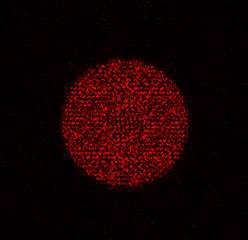 | 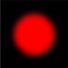 |
| Typical 1-D intensity profile (typical) | 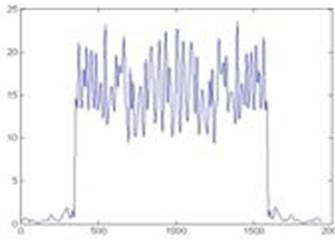 | 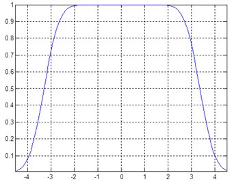 |
Additional remark: The “noisy” oscillations or speckled output intensity profile of the diffuser in the Gaussian input case is due to interference. Nevertheless, many metrology applications benefit from speckled pictures. For material processing applications, the thermal distribution of energy is more important than a point intensity value. There is also a natural smoothing effect in many (but not all) applications, which erases most signs of fluctuations.
Click here and contact us for more information.
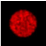
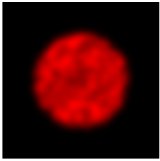
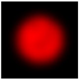
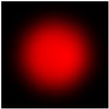
Effect on output shape – comparison between different beam qualities (M2 values)
- Edge of the shape becomes wider
- Speckles are reduced and intensity profile becomes more uniform
| M2 = X (low) | M2 = 2*X | M2 = 4*X | M2 = 8*X |
 |  |  |  |
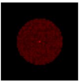
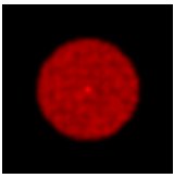
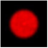
Zero-Order effect:
The figures below show the Zero-order for the same element with different M2 values of input beam. One can see that with a low M2 input beam the Zero-order is concentrated in a smaller area, causing it to look much stronger than its neighboring area.
| M2 = X (low) | M2 = 2*X | M2 = 4*X |
 |  |  |
High homogeneity series (RH/HH/XH)
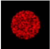
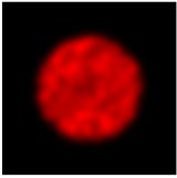
Holo/Or developed a new class of diffusers/homogenizers with enhanced performance referred to as the high homogeneity series (Homogeneity can be defined as the average intensity over an area unit). Its advantages are higher homogeneity, and lower zero order. This corresponds well with input beams of lower M2, and for applications where it is impossible to use a Top-Hat beam shaper product.
This DOE design includes two diffractive surfaces. The first decreases the coherence of the incident beam and the second surface shapes the beam.
Advantages and disadvantages of HH relatively to HM are displayed in below table:
| parameter | HH vs. HM |
| Homogeneity | Much better |
| Efficiency | Slightly less |
| Zero Order | Significantly reduced |
| Transfer region | Larger |
This can be illustrated with the figures below:
| HM | HH |
 |  |
Application example - Optical Setup with MM fiber
The optical setup below shows a laser coupled to a MM fiber to achieve uniform intensity distribution in the far field or alternatively in the focal plane when used with a focusing lens.
The number of modes in the output is proportional to the fiber length and core diameter. Each mode of the fiber’s output will propagate through the diffractive Homogenizer to create an interference pattern in the focal plane. However, in contrast to a single-mode beam, the multi-mode contains many of these modes. Each mode is creating a different pattern that overlap with each other. In the focal plane, this creates a well-averaged uniform output. The setup does not require any specific property of the laser beam parameters.

Installing / sensitivity for mechanical tolerances
| Parameter | Effect | Comments |
| Z-translation (along optical axis) | Not sensitive | As long as all diffracted rays enter the focusing element |
| X-Y translation | Not sensitive | |
| Tilt X,Y | Zero Order slightly increases | |
| Tilt Z | Not sensitive | Output shape rotates |
| Incident beam size | Not sensitive | Have to be larger than minimum defined in spec |
| Polarization | No effect |
FAQs
Q: What is the difference between Top-Hat beam Shaper and Diffuser?
A: Comparison table between TH and HM:
| Parameter | Top Hat element | Diffuser / Homogenizer element |
| Incident beam | M2 <1.3(TEM00) | Any |
| Output shape | Any | Any |
| Output Shape precision | Excellent | Good |
| Uniformity | Very good | Depends on input beam, more uniform with larger M2 of input |
| Edge steepness (transfer region) | <= diffraction limited spot | Depends on M2 of input beam less steepness with larger M2 of input) |
Q: What will happen if I use other laser wavelength than specified (designed) wavelength?
A: Using a diffuser element at a wavelength other than the design:
- Each diffuser element is manufactured to be wavelength-specific. The diffractive etching pattern is unique for a given diffusion angle at a given wavelength. Therefore, using a diffuser element at a wavelength other than the design will result in a new diffusion angle as well as output beam size, proportional with the ratio of ~used λ / design λ.
- The etching depth is optimized for a certain design wavelength, and use at another wavelength will cause energy migration in the beam, with some portion of the diffused power moving to the non-homogenized zero order, appearing as a central peak in output beam.
Nonetheless, our mask inventory can be used flexibly to produce a wide variety of diffusion angles over a wide wavelength spectrum, and only our etching process need to be optimized per requirement/customer.
Q: What is the recommended distance between DOE to the focusing lens? Can it be few millimeters?
A: For HM elements the distance between the DOE and a Focusing system is not important, as long as the clear aperture of the Focusing system will be large enough (~1.5 x HM size at lens position) to prevent energy losses due to truncation.


