ELONGATED FOCUS CONTENTS
INTRODUCTION
A diffractive Elongated Focus (EF) element creates a Bessel Beam, which can then be focused using an external lens. When focused, Bessel beams have a far longer depth of focus compared to a Gaussian beam, with a corresponding decrease of energy density at focus. This application note is meant to aid the user’s understanding of the functionality and considerations when using a diffractive elongated focus element.
Operation Principle
One can explain the performance of a diffractive Elongated Focus by using a model of a Multifocal lens. A diffractive Multifocal lens is a commonly used optical element in laser applications and eye surgery (where the intraocular lens is normally a multifocal lens). Basically, a multifocal element splits an incident beam into a few portions and adds to each portion a different optical focusing power, so that each portion is focused a different position along the optical axis. The diffractive Elongated focus element works similarly, but instead of discrete splitting to a specific number of foci, it generates a continuous function. Thus, the incident beam focuses continuously along the optical axis. Conceptually one could describe this as if a very large amount (infinite) of portions of the input energy are focused on different position very close (infinitesimal distance) to each other along the optical axis, creating the elongated focus effect.
Note: it’s important to understand that each discrete portion has a small depth of focus. So for each plane along the optical axis a small amount of energy will be in focus and the rest of the energy will be out of focus. The energy that is not in focus appears as low energy rings or lobs around a high central spot.
Theory
For a normal Gaussian laser beam, the depth of focus can be defined by the following formula:

- Δ – is the energy density drop
- ZRx is Raleigh length:

- M2 is beam quality factor
- d is the beam diameter at e-2
- F is the external lens EFL
- λ is the laser wavelength
When using diffractive Elongated Focus, the length of the focal region is determined by the element angle, the external lens focal length and the beam diameter.
In theory it is possible to make a design to generate a very long depth of focus, but at the cost of reduced energy density in the central spot. This reduction is what will limit the usefulness of such a design. Typically, a small focus elongation is sufficient to improve the process without making significant changes in the optical setup. This can be achieved without the need of replacing the laser or changing the focal distance.
Changing the depth of focus
The depth of focus is scalable for different focusing lenses per the following relation:
 Where:
- Δ: is the depth of focus
- Δ0: is the initial depth of focus
- λ: is the operating wavelength
- λ0:is the initial wavelength
- fr: is the EFL of the system
- fr0 is the initial EFL of the system
Another option to change the DOF is by varying incident beam size:

Where w0 is the initial beam size.
For small changes in the depth of focus we suggest using the binary type elongated focus elements. The depth of focus of these elements increases by a factor ~1.5x compared to the system depth of focus without them.
Basic rules:
- Increasing EFL = DOF increases
- Increasing beam size = DOF decreases
Click here and contact us for more information.
Positive vs. Negative Elongated Focus
In the images below, we see the difference in the location of the extended depth of focus (DOF) in the Negative and Positive Elongated Focus set-ups. The DOF of the Negative EF occurs after the lens focal plane, and the DOF of the Positive EF occurs before the lens focal plane.
Set-Up without Elongated Focus

Negative Elongated Focus

Positive Elongated Focus

Examples
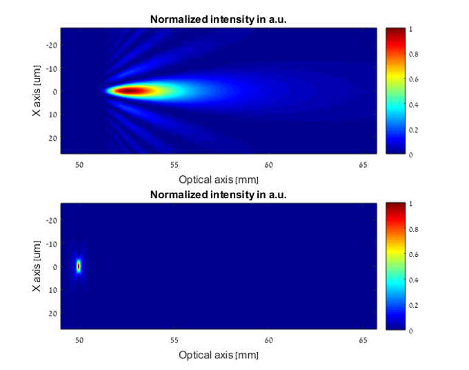
Example 1: Elongated focus vs. Gaussian beam
- Gaussian beam 5 mm
- EFL 50 mm
- Wavelength 532 nm

Figure 1: Upper image using Elongated focus element, lower image Gaussian only
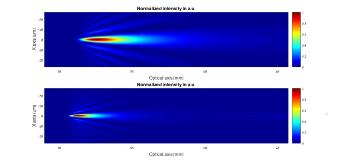
Example 2: Comparison of DOF for different incident beam sizes

Figure 2: Upper image beam size 5 mm, lower image beam size 10 mm
Example 3: Using different EFL
EFL 100 mm

Figure 3: Intensity distribution generated with elongated focus element on the X-Z plane


